RIAA Record Preamplifier
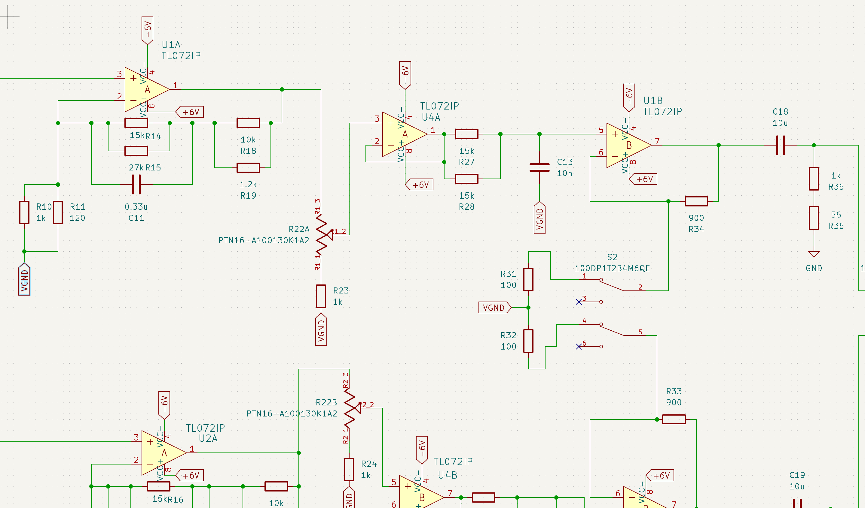
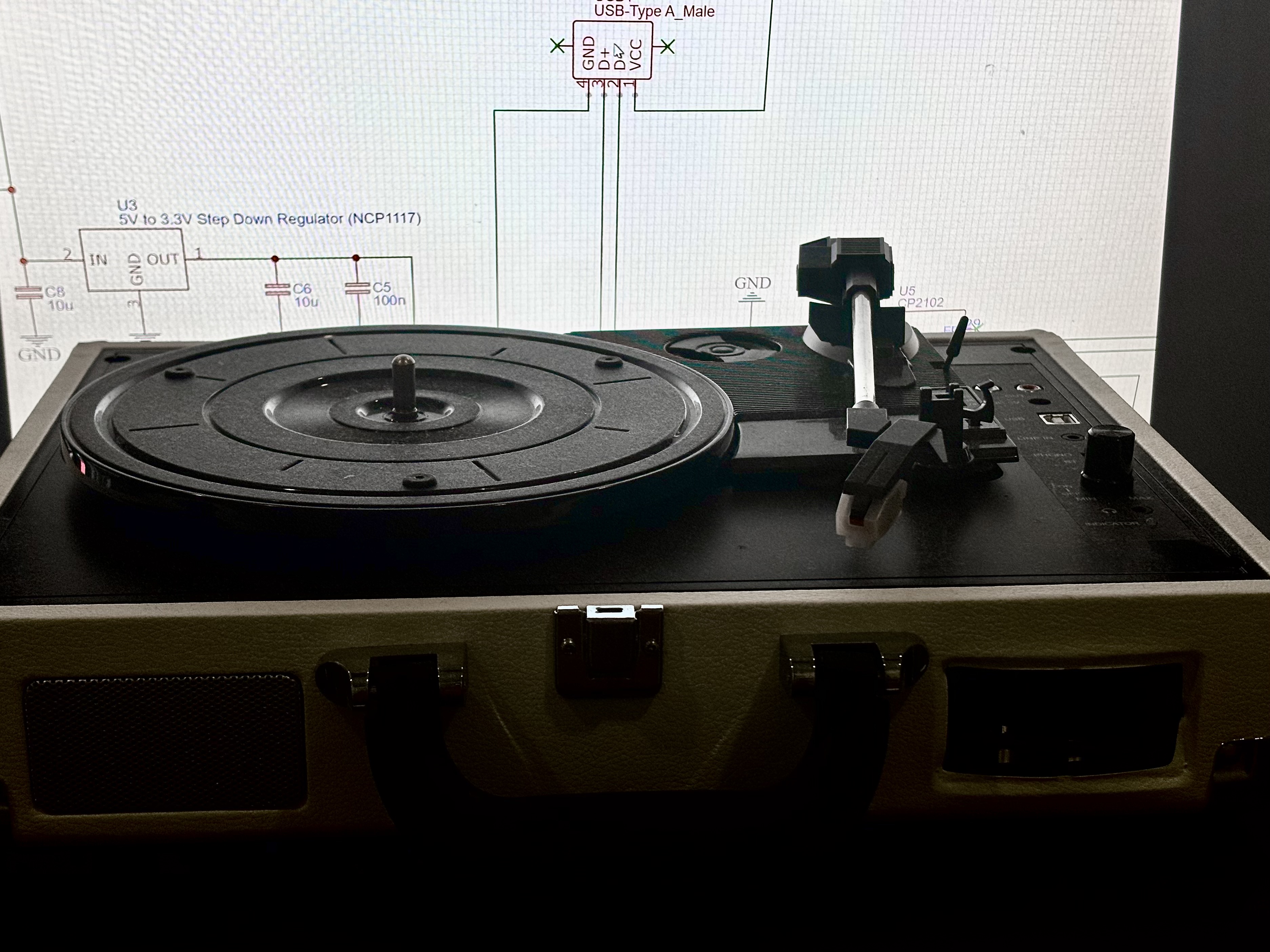
This record preamplifier is design to take a signal from either of a magnet cartridge, a coil cartridge, or a ceramic cartridge (each with differing impedance matching requirements and input stage factors) and amplify it while applying a mix of passive and active filter correction to the signal to match the RIAA standard for record cutting equalization. The circuit is built on TL072 low noise operational amplifiers and implements an active base and treble equalization with a passive top end curve.
The project spanned 3 weeks from inception, to research, to design,
to digital verification and finally prototype manufacturing which was
conducted in the Melbourne University Telstra Creator Space. The key
challenge of the project was mathematically verifying a novel filter
network design instead of copying one of the many designs
online.
This process began with searches on Instructables and other online
forums, and really kicked off when I came across a widely read
paper written by Stanley P. Lipschitz’s. From this paper, I split
on of the papers 4 pole active filter networks into a two pole active
and one pole passive network that I was able then able verify with a calculus
2 level of mathematics. After mathematical verification, I recreated the
design in LTSpice, where I verified the filter curve will be what I
expected in practice.
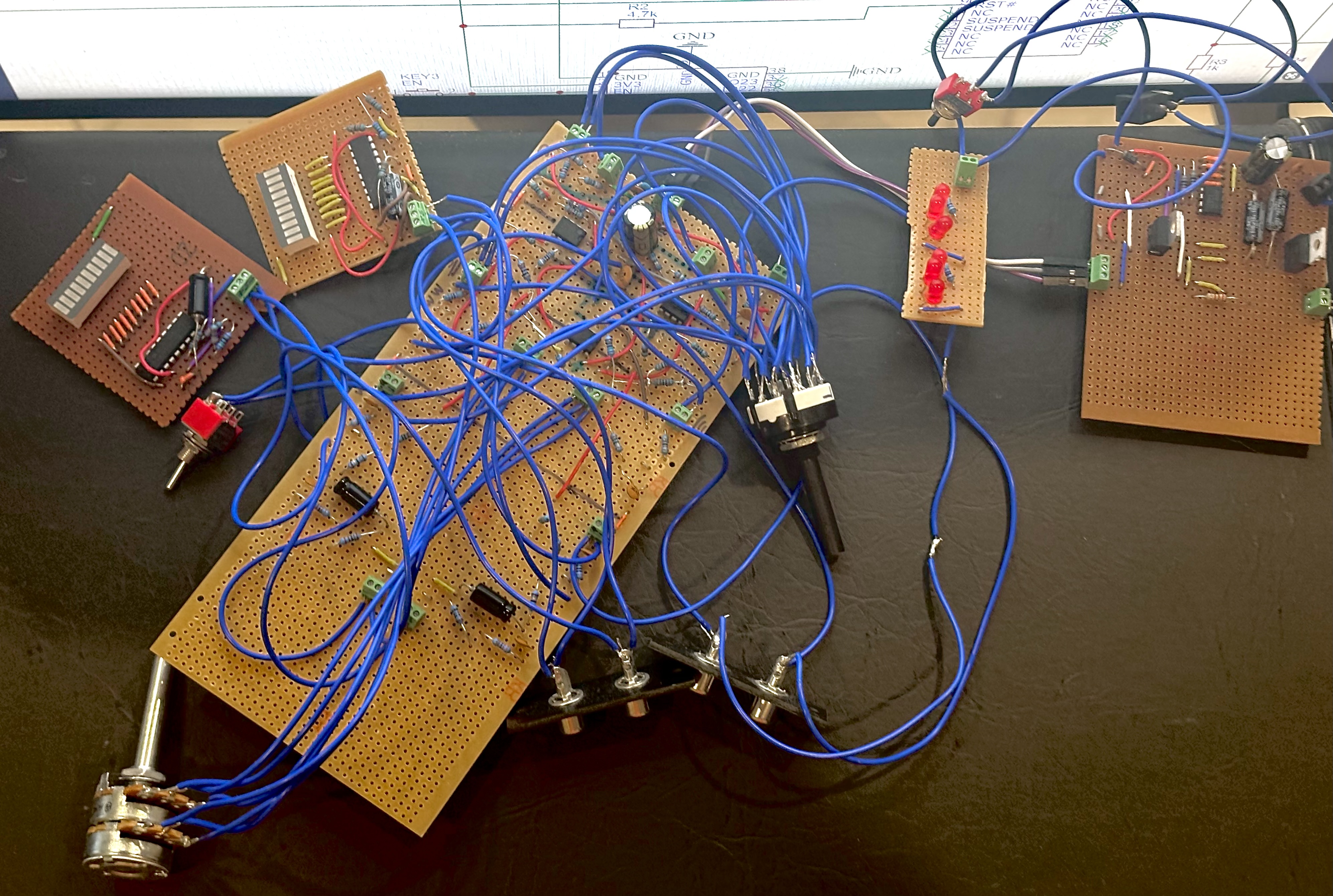
The prototype constructed demonstrated a significant flaw in the
build process, as the audio reconstructed lacked upper frequency clarity and
consistency across the left and right channels. Upon troubleshooting
and verifying component correctness and function with an oscilloscope and
multimeter, it was concluded that the design implementation on stripboard
introduced unintended resistance and capacitance in the long wire runs
and many solder connections across the board. The design was considered too
expensive for its functionality to warrant the order of a custom PCB.
LTSpice
Autodesk Fusion
oscilloscopes and multimeter
Through hole soldering tools