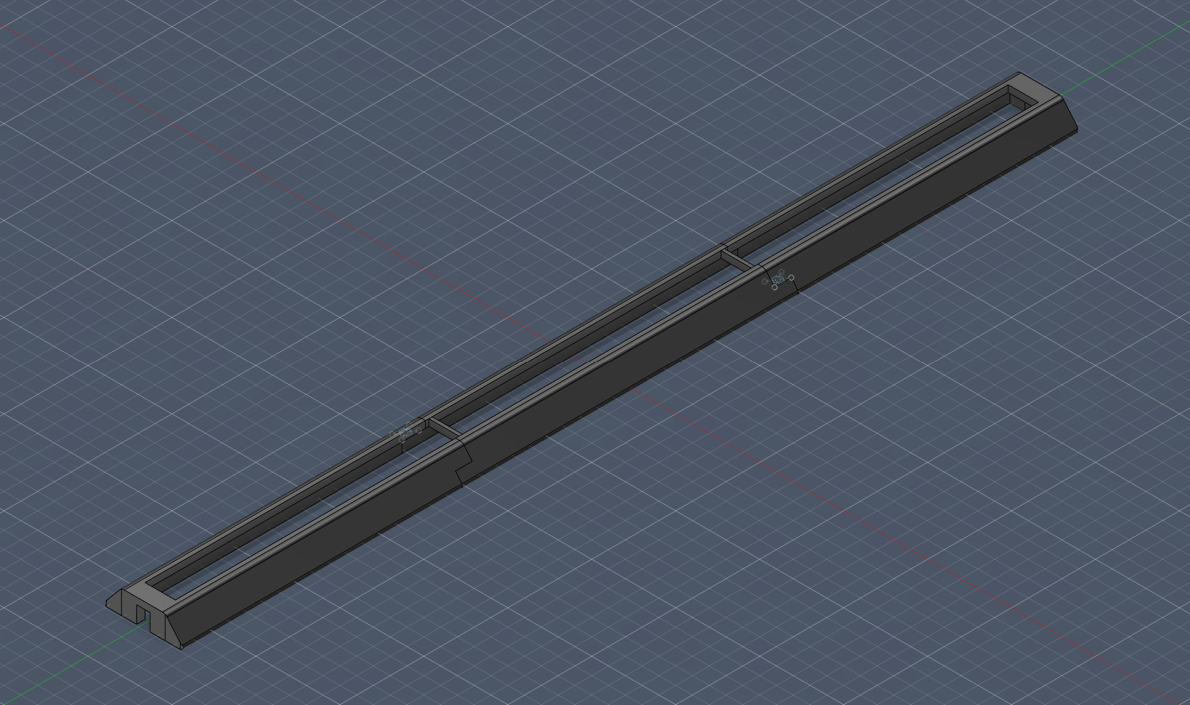
Wall Mounted Spectrum Analyser
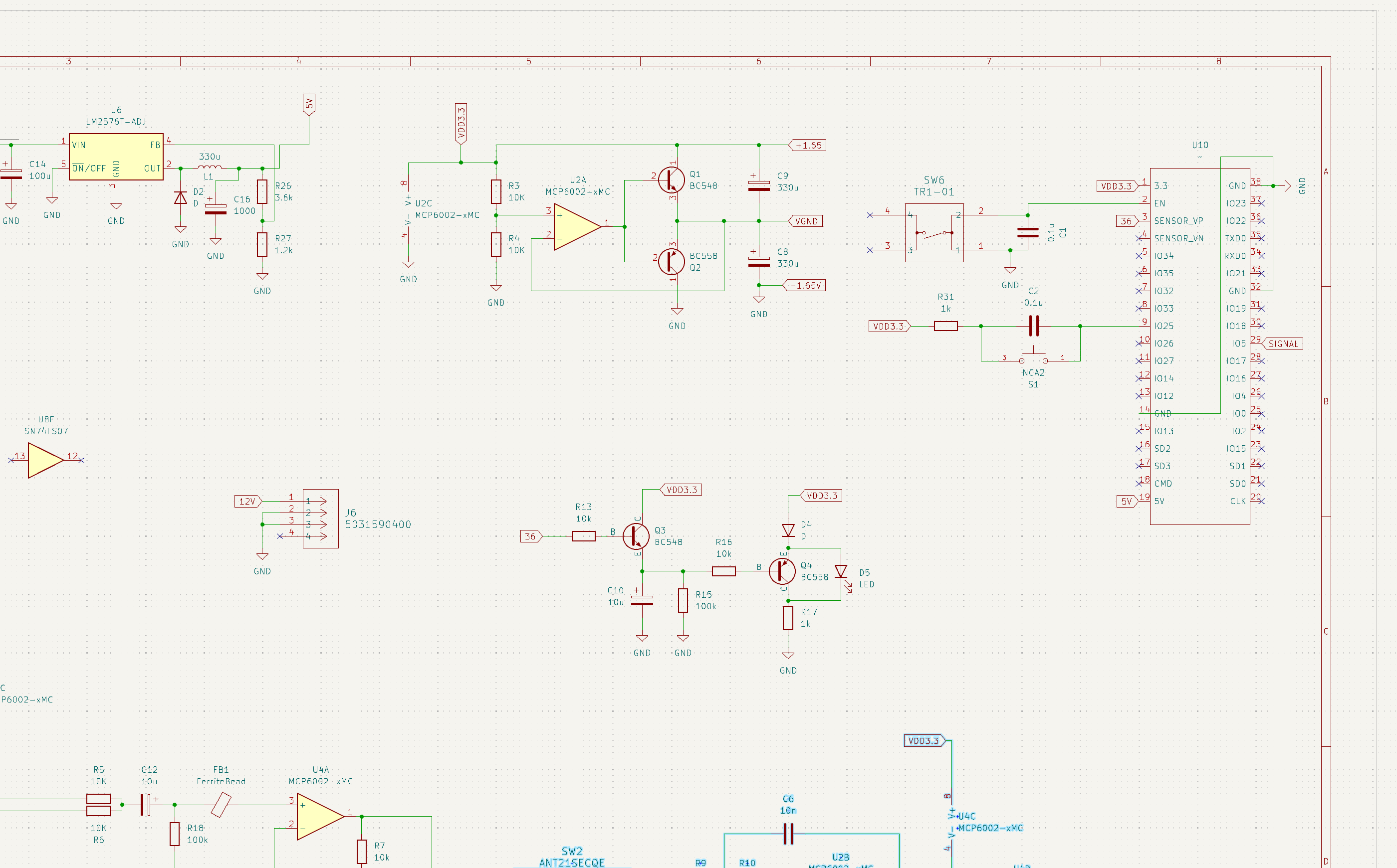
The Wall Mounted Spectrum Analyser is a 16 channel display of the Fourier transform applied to an input signal. The project covers three stages, those being: the amplification and filtering of the input signal from a electret microphone or a 6.5mm jack; the processing of the signal and creation of a logarithmically scaled 16 channel representation of the signal in the frequency domain; then finally, writing that information to a strip of chained WS2815 individually addressable LEDs.
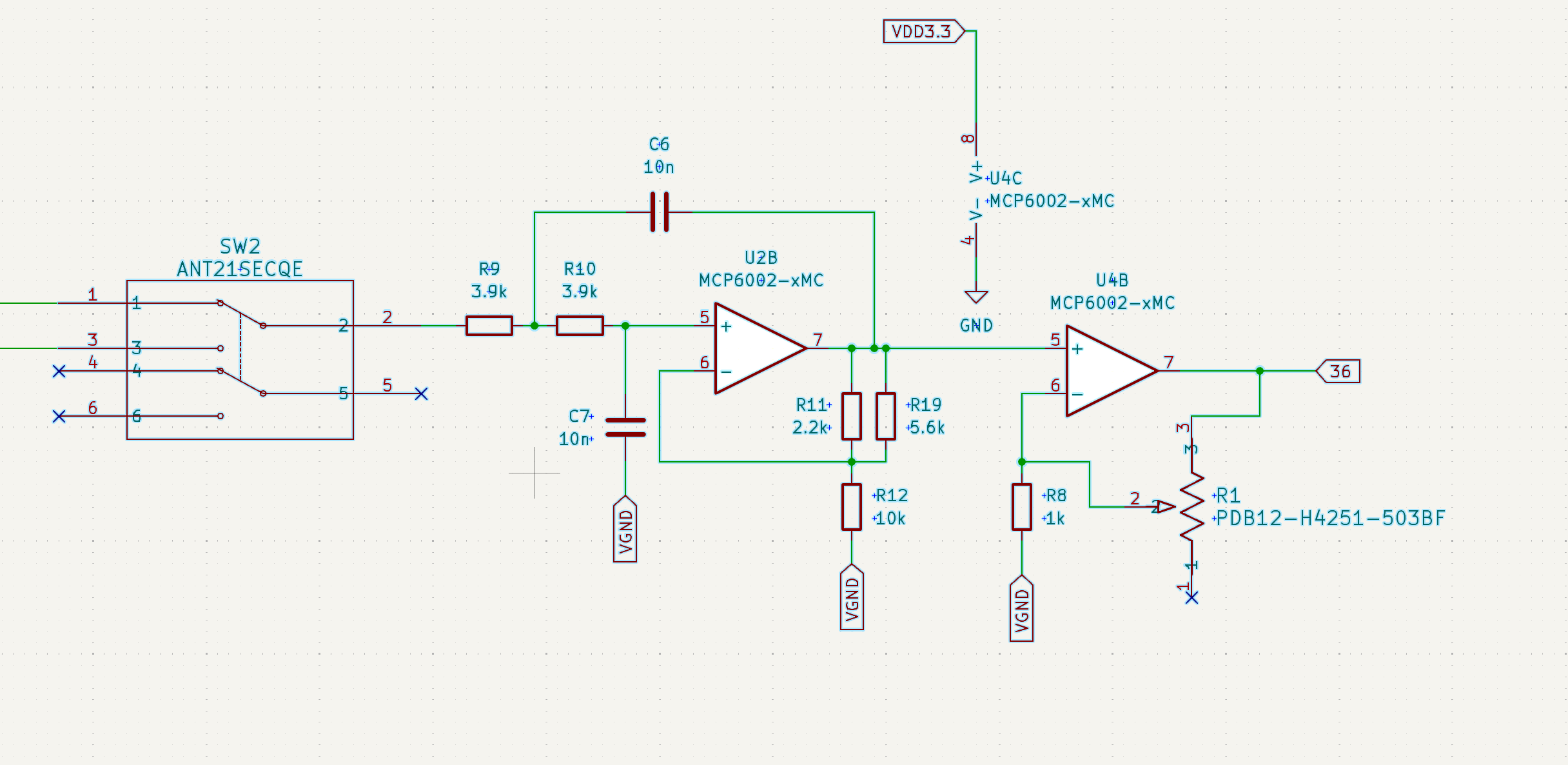
The input stage includes a two stage op-amp circuit, where the first
stage is different for each of the input methods. For the electret
microphone, the first amplification stage was a dual 1000x amplification
chain. For the 6.5mm connection, the left and right channels were buffered before
receiving 10x amplification. The second amplification stage is a
combination of a low pass Sallen-Key topology active filter and a
variable gain amplification circuit for volume control. The input stage
was simulated using LTSpice and correctly filtered and amplified the test signal.
The signal processing stage underwent many redesigns and scope reductions, as the
original design was constructed with an arduino micro-controller with a frequency
range of 20Hz-20KHz. The ATMega chip used in the arduino design cannot be clocked
fast enough to read and process 20KHz data, therefore the design was updated to use
the ESP32 WROOM-32 platform. While the platform boasts a clock speed of ~300MHz compared
to the 16MHz of the arduino system, programming the ESP32 using the arduino IDE
added significant time to each process cycle (as the compatibility layer could not
take advantage of the ESP32's simultaneous analog input or signal generation functions ).
Therefore, I had to pivot again and learn the ESP-IDF development environment. While I still couldn't
reliably achieve a range of 20-20Khz, I could create a functional prototype with a range of
20-4KHz which covers a majority of the widely used frequencies in music.
The final element was the display. The original design used WS2812 LED strips,
however, these strips could not provide the current required to chain a large number together,
and power injection along the strip did not seem to improve the performance
of the strip. This is down to the 5V operating voltage. Therefore, WS2815 LED strips
were implemented using a 12V rail. This required a new buck converter element for the
circuit to step 12V down to 5V for the ESP32 module, but resulted in brighter LEDs at the
end of the strip.
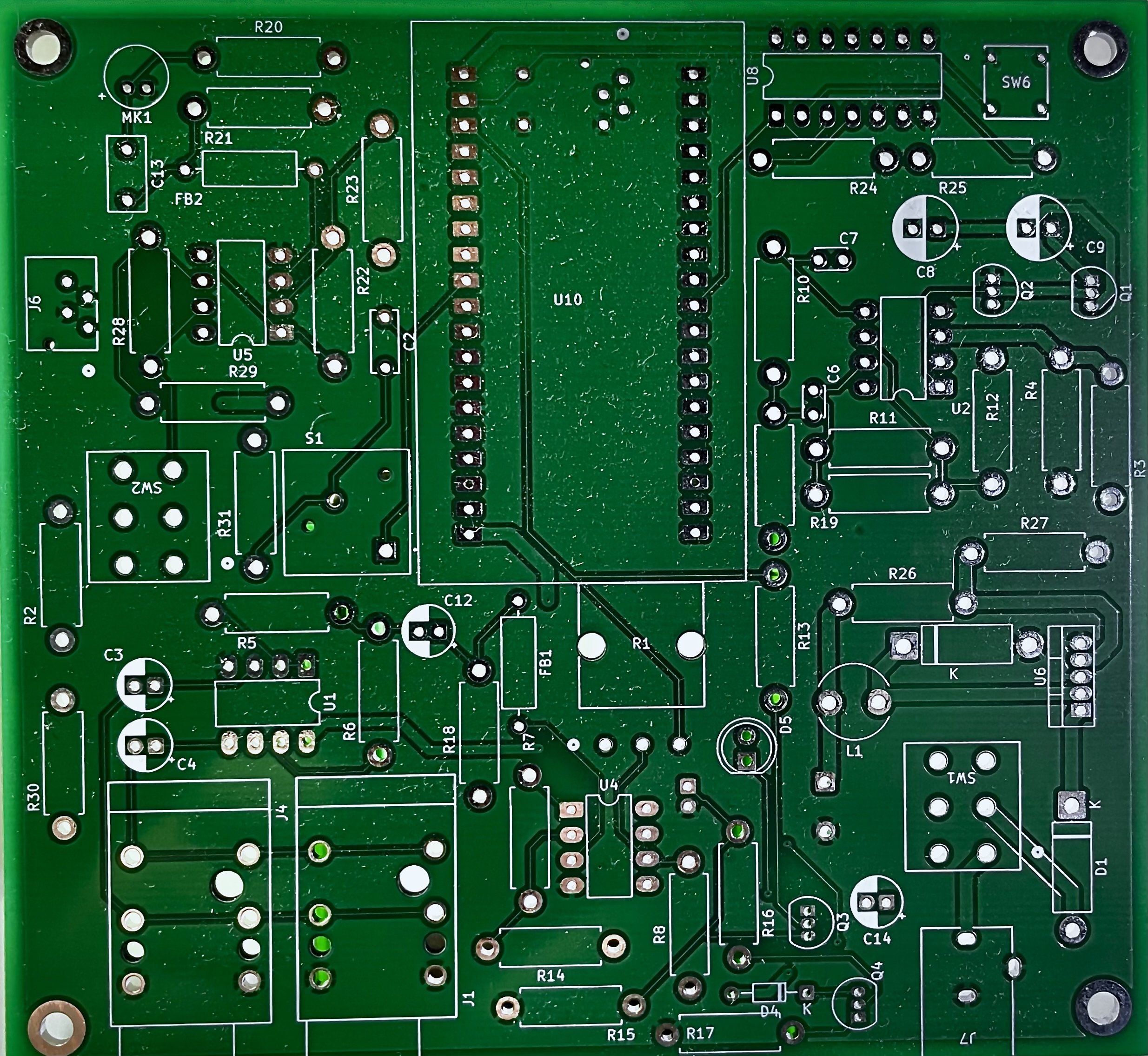
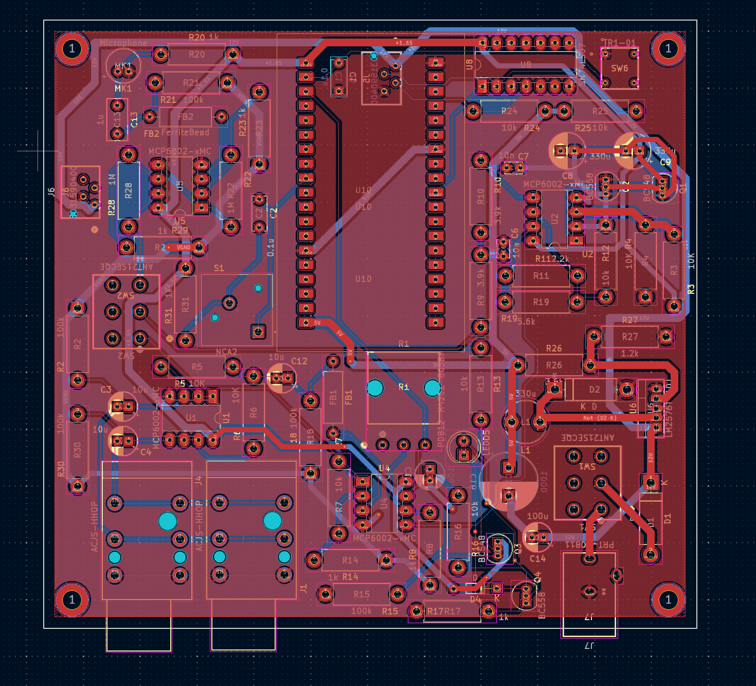
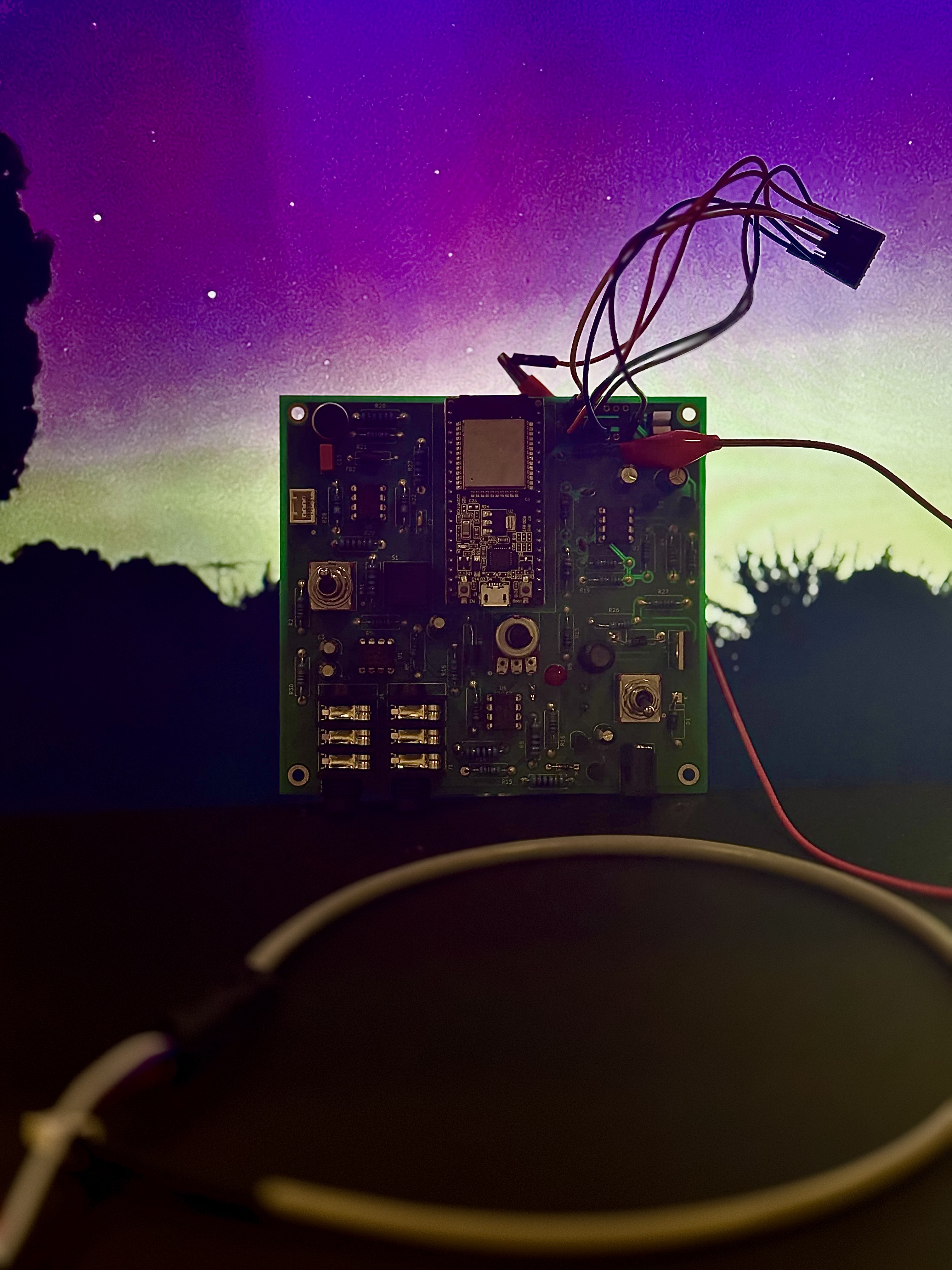
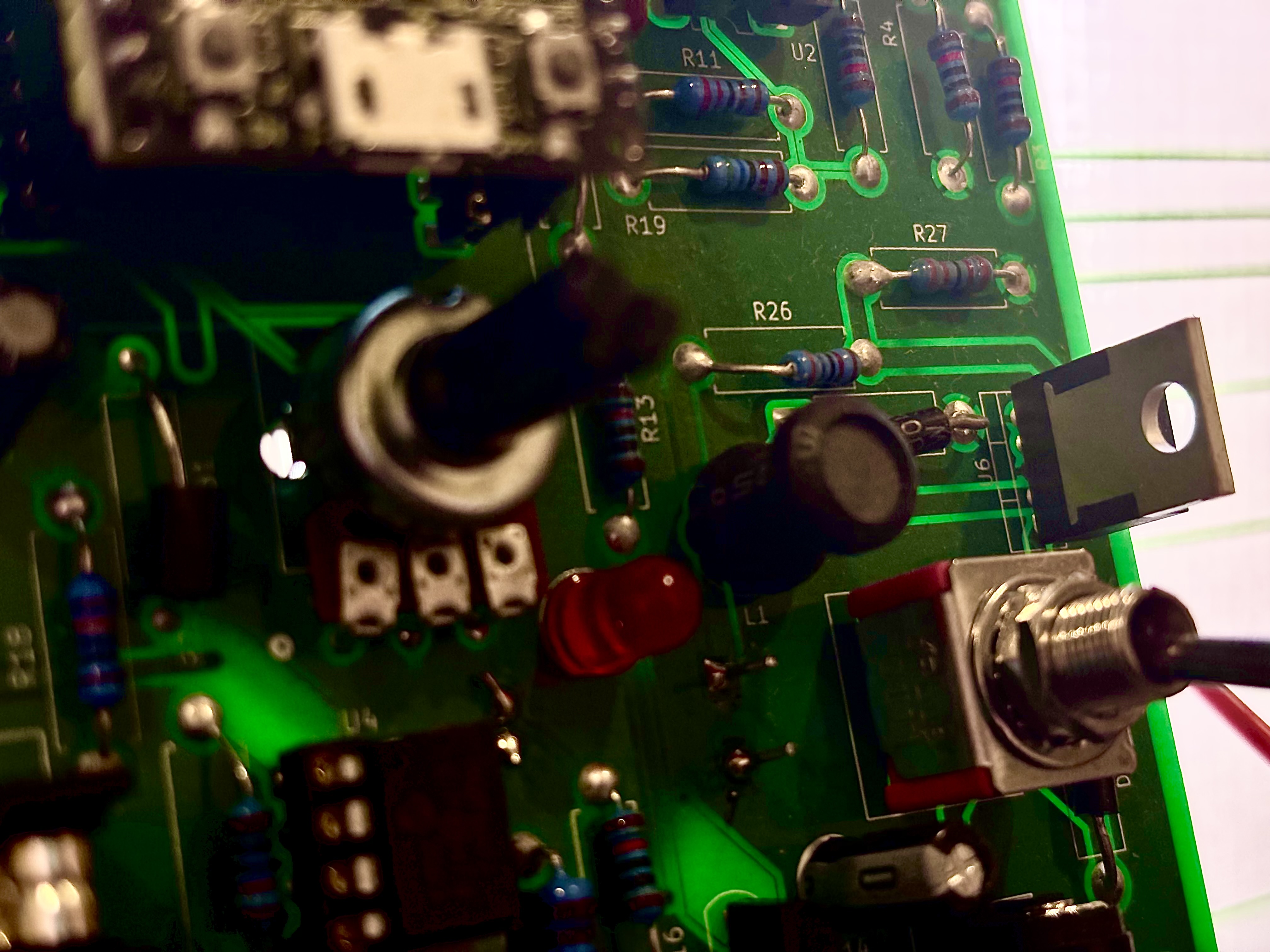
This project was also my first attempt at ordering a custom PCB. The PCB was developed
in KiCad designer and ordered through JLCPCB. The design was mostly functional with
one key issue. A batch of hex buffer DIP8 ICs used to step up the logic signal from 3.3V to 5V for the
WS2815 LEDs did not function correctly within the PCB design. After further
verification and testing I concluded that the ICs were being driven correctly
according to the specification, however a continuity test on the ICs demonstrated
that there were incorrect connections between some pins. As the ICs were not bought
from a reputable supplier, it is likely they were poorly made dupes that did not function
to datasheet specifications.
Autodesk Fusion
Visual Studio Code
ESP-IDF
Through hole soldering
EDP-IDF
ESP32