
Unmanned Ground Vehicle
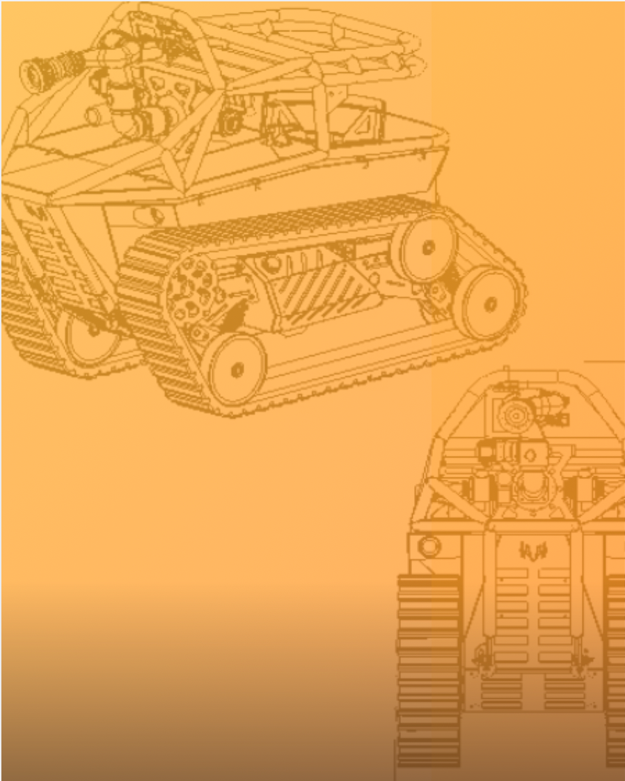
The Unmanned Ground Vehicle is a tracked autonomous unit designed for area mapping in mining. Currently in the prototype phase, the unit is capable of basic object avoidance while generating a point cloud of the surrounding area using time of flight(TOF) sensors actuated on servo plates.
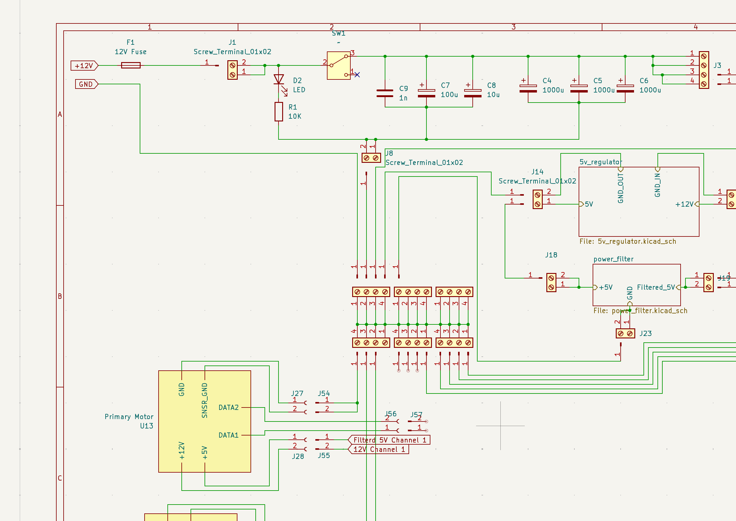
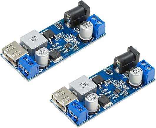
I am part of the power system and PCB design team, which designed both a tethered and untethered power chain including two power rails for logic level devices and high power devices. The logic level power network is separated with capacitor banks and LC filters to support precise sensor readings. The system was constructed within a 2 week timeframe, therefore makes use of off the shelf step down converter modules, however the power bank modules and filtering module were constructed on campus in the Telstra Creator Space. As a member of the power systems team, the project involved constant discussion with the driver motor team. Especially as the project included three re-specifications of the driver motors as last minute changes in the supply chain forced a scaled back approach to the track design. However, by the end of semester one the team successfully powered both main driver motors as well as the main processor board.
KiCad Designer
OnShape CAD
Through hole soldering
C/C++
Rasberry Pi 0
Rasberry Pi Pico